Understanding Network Devices
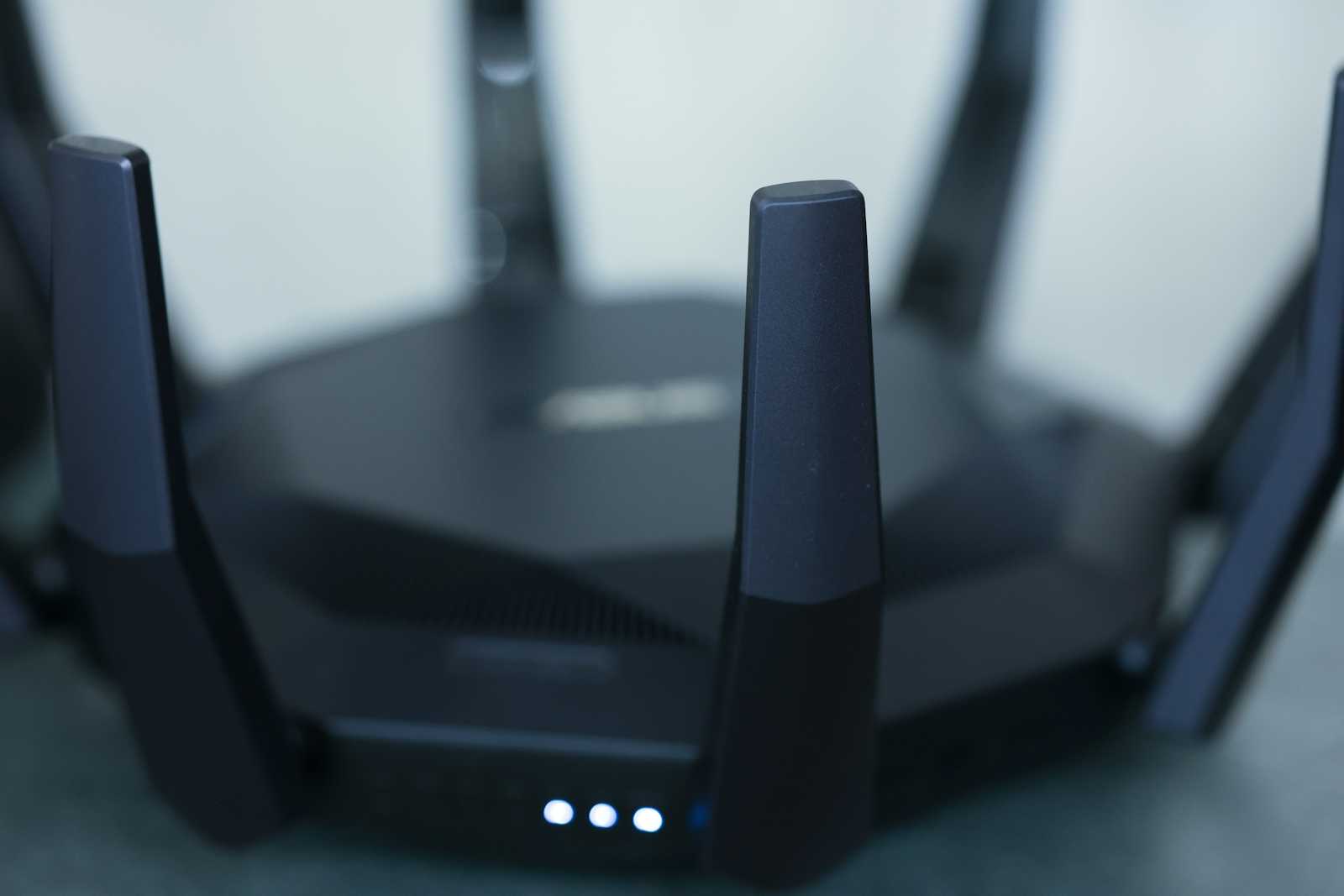
Let me walk you through how networks actually work, from your internet connection all the way to production server infrastructure.
The Big Picture: How the Internet Reaches You
Imagine your computer wants to load a website. Here's the journey that request takes:
Your computer sends data to your router
The router sends it to your modem
The modem sends it to your ISP (Internet Service Provider)
The ISP routes it across the internet to the destination server
That server might sit behind a firewall, connected through a switch, and accessed via a load balancer
Each device has a specific job. Let's understand them one by one.
1. Modem: Your Gateway to the Internet
Primary Responsibility: Convert between different signal types to connect your network to your ISP.
Think of a modem like a translator at a border crossing. Your home network speaks digital Ethernet, but your ISP's cable/fiber/phone line speaks a completely different language. The modem translates between these two.
How it works:
Modulation: Converts digital data from your network into analog signals (or different digital formats) for transmission over cable, DSL, or fiber lines
Demodulation: Converts incoming signals back into digital data your network understands
The word "modem" literally comes from "modulator-demodulator"
What it does NOT do:
Doesn't assign IP addresses to your devices
Doesn't route traffic between devices
Doesn't provide Wi-Fi
Usually has just ONE Ethernet port (some have more now, but traditionally one)
Real-world setup:
Internet (ISP) <--[cable/fiber/DSL]--> Modem <--[Ethernet]--> Router <---> Your Devices
Your ISP assigns you ONE public IP address, and the modem is what terminates that connection.
2. Router: The Traffic Director
Primary Responsibility: Route packets between different networks and manage your local network.
Think of a router like a post office sorting facility. It reads addresses and determines where each package needs to go.
How it works:
Connects multiple networks together (usually your home network + the internet)
Maintains a routing table that maps IP addresses to physical connections
Performs NAT (Network Address Translation) to let multiple devices share one public IP
Assigns local IP addresses via DHCP (like 192.168.1.x)
Often includes a built-in Wi-Fi access point
The key function - NAT:
Your devices have private IPs:
- Laptop: 192.168.1.10
- Phone: 192.168.1.11
- Tablet: 192.168.1.12

Your router has:
- ONE public IP from ISP: 203.0.113.45
- Internal IP for local network: 192.168.1.1

When your laptop requests google.com:
1. Packet leaves with source IP 192.168.1.10
2. Router translates it to 203.0.113.45:random_port
3. Tracks the connection in its NAT table
4. When response comes back, translates it back to 192.168.1.10
Modem vs Router:
Modem: Connects you to the internet (one network to another network)
Router: Manages traffic within and between networks (many devices to one connection)
Many ISPs now provide combo devices that do both
3. Switch vs Hub: Local Network Connection
Both connect multiple devices on the same local network, but they work very differently.
Hub: The Dumb Repeater (mostly obsolete)
Think of a hub like shouting in a crowded room where everyone hears everything.
How it works:
Receives data on one port
Broadcasts it to ALL other ports
Every device hears every message and ignores what isn't for them
Creates collisions and network congestion
Operates at Layer 1 (Physical layer)
Why it's bad:
If Device A sends to Device B:
Hub → sends to B, C, D, E, F (everyone!)
Result: Wasted bandwidth, security issues, collisions
Switch: The Smart Director
Think of a switch like a postal worker who knows exactly which mailbox each letter goes to.
How it works:
Learns which devices are connected to which physical ports
Maintains a MAC address table (also called CAM table)
Forwards frames only to the destination port
Operates at Layer 2 (Data Link layer)
Dramatically reduces collisions and improves performance
MAC address table example:
Port 1: MAC aa:bb:cc:dd:ee:01 (Server 1)
Port 2: MAC aa:bb:cc:dd:ee:02 (Server 2)
Port 3: MAC aa:bb:cc:dd:ee:03 (Server 3)

When Server 1 sends to Server 2:
Switch → looks up MAC table → forwards ONLY to Port 2
Switch vs Hub:
Hub: Broadcasts to everyone (10 Mbps typical, shared bandwidth)
Switch: Targeted delivery (1+ Gbps per port, dedicated bandwidth)
Modern networks use switches exclusively
Typical office/data center setup:
Router (192.168.1.1)
    |
    | Port 24
    |
Switch (24 ports)
    |
    |--- Port 1: Computer A
    |--- Port 2: Computer B
    |--- Port 3: Computer C
    |--- Port 4: Printer
    ... etc
4. Firewall: The Security Gate
Primary Responsibility: Control what traffic can enter or leave your network based on security rules.
Think of a firewall like a security checkpoint at an airport that checks credentials and decides who gets through.
How it works:
Inspects packets based on rules (IP addresses, ports, protocols, content)
Can operate at multiple layers (network, transport, application)
Maintains stateful connection tracking to understand conversation context
Blocks unauthorized access, malicious traffic, and policy violations
Types of firewalls:
- Packet Filter (Layer 3/4):
Rule examples:
- ALLOW tcp from any to 192.168.1.100 port 80
- DENY tcp from any to any port 23
- ALLOW tcp from 192.168.1.0/24 to any port 443
- Stateful Firewall: Tracks connections, not just individual packets:
Connection: Client 203.0.113.5:54321 → Server 192.0.2.10:443
State: ESTABLISHED

Firewall remembers this connection and allows return traffic
- Application Layer Firewall (WAF): Inspects HTTP/HTTPS content, can block SQL injection, XSS, etc.
Where firewalls live:
Network perimeter: Between your network and the internet
Host-based: Software on individual servers (iptables, Windows Firewall)
Cloud: Security groups (AWS), firewall rules (GCP), NSGs (Azure)
Real-world example:
Internet
    |
Firewall (allows only ports 80, 443, 22 from specific IPs)
    |
Load Balancer
    |
Web Servers (can only be accessed through load balancer)
5. Load Balancer: The Traffic Distributor
Primary Responsibility: Distribute incoming requests across multiple servers to handle scale and provide redundancy.
Think of a load balancer like a restaurant host who seats guests at different tables to balance the workload across waiters.
Why you need it:
One server can't handle millions of requests
Provides redundancy (if one server dies, others keep working)
Enables zero-downtime deployments
Optimizes resource utilization
How it works:
Basic distribution algorithms:
- Round Robin: Cycles through servers sequentially
Request 1 → Server A
Request 2 → Server B
Request 3 → Server C
Request 4 → Server A (cycle repeats)
- Least Connections: Sends to server with fewest active connections
Server A: 45 connections
Server B: 23 connections ← sends here
Server C: 67 connections
- IP Hash: Same client always goes to same server (session affinity)
hash(client_ip) % num_servers = destination
203.0.113.45 always → Server B
Layer 4 vs Layer 7 Load Balancing:
Layer 4 (Transport):
Looks at IP addresses and TCP/UDP ports only
Fast, lightweight
Can't make routing decisions based on content
All traffic to port 443 → distribute across web servers
Layer 7 (Application):
Inspects HTTP headers, URLs, cookies
Can route based on content
More CPU intensive
/api/* → API servers
/images/* → CDN servers
/admin/* → Admin servers (with authentication check)
Health checks:
Load balancer periodically checks each server:
- HTTP GET /health every 10 seconds
- If server responds 200 OK → healthy
- If server times out or errors → mark unhealthy, stop sending traffic
Popular load balancers:
Hardware: F5, Cisco
Software: HAProxy, Nginx, Envoy
Cloud: AWS ELB/ALB, GCP Load Balancing, Azure Load Balancer
6. How It All Works Together: Real-World Architecture
Let's trace a request from your laptop to a production web application.
Home Network Example:
[Your Laptop] 192.168.1.10
        |
        | Wi-Fi
        |
[Router/Wi-Fi AP] 192.168.1.1
        |
        | NAT (translates private → public IP)
        |
[Modem] Public IP: 203.0.113.45
        |
        | Cable/Fiber
        |
[ISP Network] → Internet
Production Data Center Example:
Internet
    |
    ▼
[Firewall - Perimeter]
    | Rules: Allow 80, 443, 22 (from specific IPs)
    ▼
[Load Balancer - Layer 7]
    | Distributes: /api → API servers, /static → CDN
    ▼
[Switch - Core]
    |
    |----[Web Server 1] 10.0.1.10
    |----[Web Server 2] 10.0.1.11
    |----[Web Server 3] 10.0.1.12
    |
    |----[Switch - Database VLAN]
             |
             |----[Database Primary] 10.0.2.10
             |----[Database Replica] 10.0.2.11
Complete Request Flow:
1. Client makes request:
User types: https://example.com
Browser resolves DNS: example.com → 203.0.113.100
2. Request leaves client network:
Source: 192.168.1.10 (your laptop)
        ↓
Router NAT: Translates to 203.0.113.45:54321
        ↓
Modem: Converts to ISP signal format
        ↓
Internet: Routes to 203.0.113.100
3. Request enters production network:
Firewall:
  - Checks source IP: ✓ allowed
  - Checks destination port 443: ✓ allowed
  - Checks for malicious patterns: ✓ clean
  - Forwards to load balancer

Load Balancer:
  - SSL termination (decrypts HTTPS)
  - Reads HTTP headers
  - Path is /api/users → routes to API server pool
  - Checks server health
  - Picks Server 2 (least connections)
  - Forwards to 10.0.1.11

Switch:
  - Looks up MAC table
  - Port 5 has 10.0.1.11
  - Forwards frame to Port 5 only
4. Response returns:
API Server → Switch → Load Balancer
  → Firewall → Internet → ISP → Modem → Router → Your Laptop
Key Insight for Software Engineers:
When you deploy a web application, you're often working at the application layer, but understanding this infrastructure helps you:
1. Debug connection issues:
"Can't reach database" could be:
- Firewall blocking port 5432
- Switch on wrong VLAN
- Load balancer health check failing
2. Design for scale:
- Stateless applications work better with load balancers
- Session data needs sticky sessions or external storage
- Database connections need pooling (limited by switch/router capacity)
3. Security considerations:
- Never expose databases directly (keep behind firewall + private subnet)
- Use load balancers for SSL termination
- Implement application firewalls (WAF) for HTTP attacks
4. Performance optimization:
- Understand network hops add latency
- Colocate services to reduce switch/router traversal
- Use CDNs to reduce load balancer traffic
Cloud Translation:
In AWS/GCP/Azure, these devices are virtualized:
Router/Modem: VPC/Virtual Network (managed by cloud provider)
Firewall: Security Groups, Network ACLs, Cloud Firewall
Switch: Virtual networking (automatic, invisible to you)
Load Balancer: ELB/ALB (AWS), Cloud Load Balancing (GCP), Azure LB
But the concepts remain identical. When you configure a security group to allow port 443, you're configuring a virtual firewall. When you attach instances to an ALB, you're doing what a physical load balancer does.
Summary: Each Device's Core Job
Modem: Translate between your network and ISP's network
Router: Direct traffic between networks, manage local addressing
Hub: Broadcast to everyone (obsolete, don't use)
Switch: Intelligent forwarding within a network
Firewall: Security enforcement and access control
Load Balancer: Distribute traffic across servers for scale and reliability
These devices form the foundation of every network, from your home Wi-Fi to massive production systems serving millions of users. Understanding them helps you make better architectural decisions and troubleshoot issues effectively.


